1. Introduction
A hardware description language is inherently parallel, i.e. commands, which correspond to logic gates, are executed in parallel, as soon as new input arrives. A HDL program mimics the behavior of a physical, usually digital system. It also allows incorporation of timing specifications as well as to describe a system as an interconnection of different components.
2. Levels of representatino and abstraction
A digital system can be represented at different levels of abstraction

Figure 1: Levels of abstraction: Behavioral, Structural and Physical
The highest level of abstraction is the behavioral level that describes a system in terms of what it does (or how it behaves) rather than in terms of its components and interconnection between them. A behavioral description specifies the relationship between the input and output signals.
Warning = Ignition_on AND ( Door_open OR Seatbelt_off)
The structural level, on the other hand, describes a system as a collection of gates and components that are interconnected to perform a desired function. A structural description could be compared to a schematic of interconnected logic gates.

Figure 2: Structural representation of a "buzzer" circuit.
VHDL allows one to describe a digital system at the structural or the behavioral level. The behavioral level can be further divided into two kinds of styles: Data flow and Algorithmic.
Data flow: how data moves through the system(typically done in terms of data flow between registers).
The data flow model makes use of concurrent statements that are executed in parallel as soon as data arrives at the input. On the other hand, sequential statements are executed in the sequence that they are verified. On the other hand, sequential statements are executed in the sequence that they are specified. VHDL allows both concurrent and sequential signal assignments that will determine the manner in which they are executed.
3. Basic Structure of a VHDL file
A digital system in VHDL consists of a design entity that can contain other entities that are then considered components of the top-level entity.
entity - entity declaration: as the interface that defines the input and output signals.
- architecture body: the description of the entity and is composed of interconnected entities,
process and components, all operating concurrently, as schematically shown in Figure 3

Figure 3: A VHDL entity consisting of an interface (entity declaration) and a body (architectural description).
VHDL uses reserved keywords. Keywords and user-defined identifiers are case insensitive.
Lines with comments start with -- will be ignored by the compiler. (same as //)
a. Entity Declaration
The entity declaration defines the NAME of the entity and lists the input and output ports.
entity NAME_OF_ENTITY is [ generic (generic_declarations);]
port (signal_names: mode type;
signal_names: mode type;
);
end NAME_OF_ENTITY;
An entity always starts with the keyword entity, followed by its name and the keyword is. Next are the port declarations using the keyword port. An entity declaration always ends with the keyword end, optionally [] followed by the name of the entity.
NAME_OF_ENTITY - user-selected identifier
signal_names consists of a comma separated list of one or more user-selected identifiers that specify external interface signals.
mode: is one of the reserved words to indicate the signal direction:
in - indicates that the signal is an input
out - indicates that the signal is an output of the entity whose value can only be read by other entities that use it.
buffer - indicates that the signal is an output of the entity whose value can be read inside the entity's architecture
inout - the signal can be an input or an output.
type: a built-in or user-defined signal type.
bit(can have the value 0 and 1) , bit_vector(a vector of bit values)
std_ulogic, std_ulogic_vector
std_logic (resolved type) , std_logic_vector (resolved type)
boolean(TRUE or FALSE), integer, real(real values), character, time(to indicate time)
std_ulogic, std_logic can have nine values.
| 'U' - Uninitialized | 'X' - unknown (X) | '-' - Don't care. |
| '0' - Logic 0 | '1' - Logic 1 | 'Z' - High Impedance |
| 'W' - Weak siganal (can't tell 0 or 1) | 'L' - Weak Signal (should go to 0) | 'H' - Weak Signal (should go to 1) |
FYI, std_logic is derived from std_ulogic. It is a 'resolved' std_ulogic. In VHDL, if a data type does not have a function defined for it called 'resolved' than if you have two or more drivers for a signal, the compiler will complain.
Example: a<='1';
a<='1' or '0';
If signal 'a' if of type std_ulogic, then any compiler will immediately flag this code as an error.(in fact the simulator won't even let you get started).
generic: generic declarations are optional and determine the local constants used for timing and sizing the entity. A generic can have a default value. The syntax for a generic follows,
generic(
constant_name: type [:=value];
constant_name: type [:=value];
);
For the example of Figure 2, the entity declaration looks as follows.
-- comments: example of the buzzer circuit of fig. 2
entity BUZZER is
port (DOOR, IGNITION, SBELT: in std_logic;
WARNING: out std_logic);
end BUZZER;
Four-to-one multiplexer of which each input is an 8-bit word.
-- comments: Four-to-one multiplexer of which each input is an 8-bit word.
entity mux4_to_1 is
port (I0, I1, I2, I3: in std_logic_vector(7 downto 0);
SEL: in std_logic_vector (1 downto 0);
OUT1: out std_logic_vector(7 downto 0);
end mux4_to_1;
An example of the entity declaration of a D flip-flop with set and reset inputs is
-- comments: example of the declaration of a D flip-flop with set and reset inputs
entity dff_sr is
port (D, CLK, S, R: in std_logic;
Q, Qnot: out std_logic);
end dff_sr;
b. Architecture body
The architecture body specifies how the circuit operates and how it is implemented. As discussed earlier, an entity or circuit can be specified in a variety of ways, such as behavioral, structural (interconnected components), or a combination of the above.
architecture architecture_name of NAME_OF_ENTITY is
-- Declarations
begin
-- Statements
end architecture_name;
Behavioral model
The architecture body for the example of Figure 2, described at the behavioral level,
architecture behavioral of BUZZER is
begin
WARNING <= (not DOOR and IGNITION) or (not SBELT and IGNITION);
end behavioral;
The header line of the architecture body defines the architecture name, e.g. behavioral, and associates it with the entity, BUZZER. The main body of the architecture starts with the keyword begin and gives the Boolean expression of the function. The "<=" symbol represents an assignment operator and assigns the value of the expression on the right to the signal on the left.
The behavioral description of a two-input AND gate is shown below.
entity AND2 is
port(in1, in2: in std_logic;
out: out std_logic);
end AND2;
architecture behavioral_2 of AND2 is
begin
out1 <= in1 and in2;
end behavioral_2;
A two-input XNOR gate
entity XNOR2 is
port (A, B: in std_logic;
Z: out std_logic);
end XNOR2;
architecture behavioral_xnor of XNOR2 is
-- signal declaration (of internal signals X, Y)
signal X, Y: std_logic;
begin
X <= A and B;
Y <= (not A) and (not B);
Z <= X or Y;
end behavioral_xnor;
Concurrency
It is worth pointing out that the signal assignments in the above examples are concurrent statements. This implies that the statements
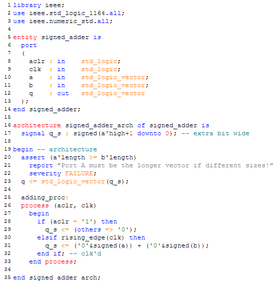
A Signed Adder


